|
Morse Micro IoT SDK
2.9.7
|
|
Morse Micro IoT SDK
2.9.7
|
This section describes the binary protocol used by the Machine-to-Machine Interface (M2M) for communication between an Agent and a Controller.
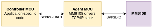
The diagram below shows the roles of the Agent and Controller. The Agent connects to the Morse transceiver and implements the drivers and network stack. The Controller runs application code and controls the Agent via the M2M protocol.
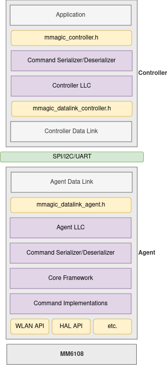
The following diagram shows the M2M interface protocol software stack. At the top of the stack is the application code that runs on the Controller. This interacts with the Controller library via the Morse M2M Interface Controller API, which is defined in mmagic_controller.h. The Controller library takes care of serializing and deserializing data for communication with the Agent. It implements the controller side of the "Link Layer Control (LLC)" protocol that is responsible for multiplexing and synchronizing commands, responses, and events.
Actual communication between the Controller and the Agent is the responsibility of the data link layer. This layer provides a semi-reliable transport for communicating packets asychronously between the Controller and Agent. Because the data link implementation is platform and hardware dependent it needs to be implemented on a per-platform basis. Protocols are currently defined for SPI and UART transports (see M2M SPI Data Link Protocol and M2M UART Data Link Protocol respectively). On the Controller side, the Morse M2M Interface Controller Data Link API provides the interface between the Controller library and the data link implementation.
The M2M SPI Data Link protocol is asymmetric. The Controller acts as SPI master and the Agent acts as SPI slave. The protocol uses 6 pins for communication:
| Pin Name | Direction | Description |
|---|---|---|
| SPI MISO | Agent->Controller | SPI data: master in, slave out |
| SPI MOSI | Controller->Agent | SPI data: master out, slave in |
| SPI CLK | Controller->Agent | SPI clock |
| SPI CS | Controller->Agent | SPI chip select |
| Wake | Controller->Agent | Agent wake up |
| Ready | Agent->Controller | Agent ready/IRQ |
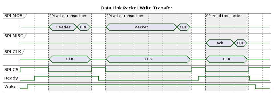
Transfers on the bus are initiated by the Controller. Two types of transfer are currently defined: packet writes and packet reads. Packet writes transfer a packet of data from Controller to Agent while packet reads transfer a packet of data from Agent to Controller.
Each transfer is made up of multiple SPI transactions. For each SPI transaction, the Controller first asserts the SPI CS pin, then transfers the data followed by a 16 bit CRC, then deasserts the CS pin. Each SPI transaction is half duplex (either a read or a write).
A packet write transfer proceeds as follows:
' Copyright 2024 Morse Micro ' SPDX-License-Identifier: Apache-2.0
A packet read transfer proceeds as follows:
A read transfer proceeds as follows:
' Copyright 2024 Morse Micro ' SPDX-License-Identifier: Apache-2.0
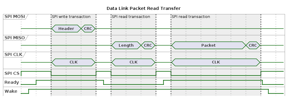
The SPI protocol is asymmetric and the Controller acts as bus master. Thus the Agent needs a means of notifying the Controller that it has a packet ready for it to read. This is done by asserting the Ready pin (driving it high) while the Wake pin is low. If the Controller detects a high level on the Ready pin while it is not asserting the Wake pin then it knows that it needs to perform a packet read transfer.
If the Controller performs a packet read transfer when the Agent does not have a packet buffered for read then the Agent will return a length of zero.
The Transfer Header is written by the Controller at the start of each transfer and comprises a one octet Transfer Type field followed by a two octet Length field. The use of these fields is defined in the sections above.
The Ack Trailer is read by the Controller at the end of a packet write transfer. It comprises a single octet indicating positive acknowledgement (CRC was valid) or negative acknowledgement (CRC or other failure).
The Length field is read during a packet read transfer and is a two octet field.
All multi-octet fields are little endian except the CRC, which is big endian.
The UART-based data link protocol is asynchronous, meaning that packets can be transmitted and received at any time. This means that the protocol is symmetrical.
When either side has a packet queued for transmission the following protocol is observed:
Packet reception mirrors transmission.
For an example implementation see mmagic/agent/m2m_datalink/mmagic_datalink_uart.c. This data link can be enabled when using the cli.c examaple application by setting the Morse Micro Persistent Configuration Store variable cli.mode to m2m.
The following diagram shows the structure of M2M packets, excluding data link layer framing.
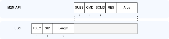
Since both sides of the protocol are implemented by the MMAGIC Agent and Controller libraries, details of these protocol layers are not documented here.